The geophone spread rolls out across a graded pad near Garden of the Gods, and within hours we are imaging what lies beneath the surface gravel. Seismic tomography in Colorado Springs works by generating a controlled wavefield—typically with a weight drop or accelerated hammer on paved sites, or a Betsy seisgun where surface access is tight—and recording arrival times across a 24-to-48-channel array. The refraction method maps P-wave velocity layering to identify top-of-bedrock and rippability zones, while high-fold reflection processing resolves deeper structure when foundation design requires it. At 6,035 feet elevation on the edge of the Front Range, Colorado Springs presents a subsurface that shifts from weathered Pierre Shale to competent Dawson Arkose within a few hundred lateral feet. A single borehole log cannot capture that transition; tomography gives us a continuous velocity cross-section that geotechnical engineers use to position spread footings, estimate cut volumes, and avoid surprises during excavation.
A single borehole tells you what is at one point; a seismic tomography line across Colorado Springs tells you what is between every point and how fast it changes.
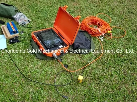
Technical details of the service in Colorado Springs
Risks and considerations in Colorado Springs
ASCE 7-22 Chapter 20 requires a measured shear-wave velocity profile to assign a Site Class, and Colorado Springs sits in a region where default assumptions can be dangerously misleading. The combination of shallow bedrock along the mountains and deep alluvial basins east of Powers Boulevard means two adjacent parcels can fall into Site Class B and Site Class D respectively, with a seismic design category shift that doubles the base shear demand. Guessing wrong costs real money in structural steel and foundation concrete. Reflection tomography provides the high-resolution P-wave section needed to plan the depth and continuity of MASW spreads, ensuring we sample enough of each velocity layer to satisfy the 100-ft minimum profile required by Section 20.4. On sites near the Rampart Range fault—a Quaternary-active structure mapped by the Colorado Geological Survey—we also use the tomography results to identify velocity anomalies that could indicate fault gouge or offset strata, flagging areas where trenching or additional investigation is warranted before heavy construction begins.
Our services
Our Colorado Springs seismic tomography program covers the full range of near-surface and intermediate-depth imaging needs, from pre-excavation rock assessment to fault-zone characterization for critical facilities.
Refraction Microtremor & Tomography for Site Class
Combined P-wave refraction and surface-wave acquisition designed specifically to satisfy ASCE 7-22 site classification requirements. We acquire parallel and orthogonal lines, merge refraction bedrock picks with Vs profiles from MASW or ReMi, and deliver a defensible Site Class letter backed by raw field records and inversion parameters.
Deep Reflection Profiling for Fault & Basin Mapping
High-fold CMP reflection surveys using a 48-channel spread and off-end impacts to image stratigraphy and potential fault offsets to depths of 150 feet or more. Appropriate for institutional and infrastructure projects where the IBC requires fault-rupture hazard assessment within the Colorado Springs metropolitan area.
Frequently asked questions
How deep can seismic tomography see in the Colorado Springs area?
With a standard 230-foot refraction spread we typically resolve the top-of-bedrock interface down to about 45–55 feet. For deeper targets, extending the spread length to 460 feet or switching to reflection-mode acquisition with a common-midpoint stack can image structure to 150 feet or more, depending on velocity contrast and background noise.
What does a seismic tomography survey cost for a typical Colorado Springs lot?
Can you run seismic lines on pavement or inside existing buildings?
Yes—on asphalt or concrete we couple geophones with a thin sand layer or adhesive baseplates, and we use a weight-drop source that does not damage the surface. Indoor surveys are feasible with shorter spreads and a sledgehammer source, though the reduced aperture limits depth penetration compared to open-ground acquisition.